In Systems with the Potential for Crossflow, Can a More Selective Gel Placement Be Achieved by Injecting a Gelant Followed by a Mobility-Matched Postflush?
(Yes, under limited circumstances.)
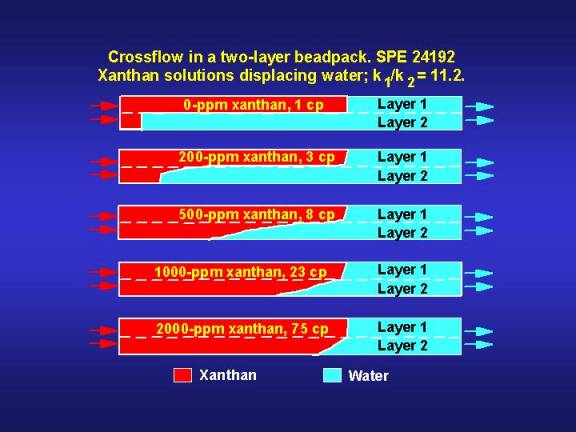
In unfractured wells, when viscous gelants are injected to displace water or relatively light oils, placement characteristics are always less desirable if crossflow can occur than if crossflow cannot occur.2,44 This point is illustrated in Fig. 18, which shows the results from five visualization experiments where various xanthan solutions were injected to displace water from a two-layer bead pack. One layer was 11.2 times more permeable than the other layer, and no restrictions to vertical flow existed between the layers.

Fig. 18 demonstrates that the degree of crossflow into the less-permeable layer increased with increased viscosity of the displacing fluid (xanthan solution). When the polymer/water viscosity ratio was greater than the permeability ratio (i.e., as for the 1,000-ppm and 2,000-ppm xanthan solutions), the average velocity for the polymer fronts was approximately equal in both layers. These finding were consistent with theoretical predictions.45,46 This behavior is excellent for a traditional polymer flood, but not for a gel treatment. As mentioned earlier, for blocking-agent applications, the distance of gelant penetration into the less-permeable zones should be minimized.
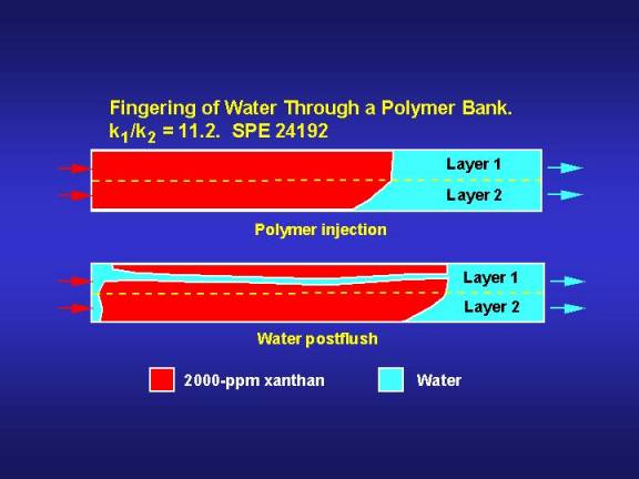
Fig. 19 illustrates the behavior seen when water was injected after placement of a 2,000-ppm xanthan solution in the two-layer bead pack. Viscous fingering occurred rapidly and almost exclusively in the high-permeability zones. More detail on this topic can be found in Refs. 2 and 44.

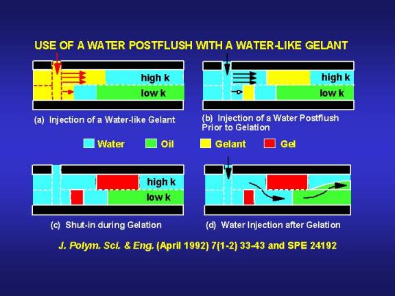
In concept, a desirable gel placement could be achieved in reservoirs where crossflow can occur.2,44,47,48 The basic idea for this placement scheme is illustrated in Fig. 20. During waterflood operations, assume that injected water has reached a production well by following a high-permeability pathway. Presumably, considerable mobile oil remains in less-permeable strata. For the first step of the gel treatment, a gelant with a water-like viscosity is injected (Fig. 20a). Because of the low viscosity of the gelant, penetration into the less-permeable zones is minimized.1,44 Second, water is injected to displace the water-like gelant away from the wellbore (Fig. 20b). Enough water must be injected so that the rear of the gelant bank in the most-permeable zone outruns the front of the gelant bank in an adjacent less-permeable zone. In the third step of the process (Fig. 20c), the well is shut in to allow gelation to occur. Finally, if the gel treatment is applied in a waterflood injection well, water injection is resumed. Hopefully, a pathway will be available for water to crossflow from the high-permeability zone into the less-permeable zone(s) so that sweep efficiency can be improved (Fig. 20d).

If this scheme is feasible, then it could provide favorable injectivity characteristics. During water injection after gelation, much of the water leaving the wellbore should enter the most-permeable zone. If the cross-sectional area is relatively large in the region where water crossflows from the high-permeability zone into the low-permeability zone (Fig. 20d), then injectivity losses from the gel treatment could be minimized (particularly for unfractured injection wells, where flow is radial). In contrast, conventional gel treatments (i.e., those with no postflush prior to gelation) in unfractured injection wells should cause significant injectivity losses1.
The "incremental" oil from this scheme could be recovered relatively quickly. As shown in Fig. 20d, oil displaced from the less-permeable zones can crossflow into the most-permeable zone, where it can flow more rapidly to the production well.47 Of course, this idea could be applied to production wells, to injection wells in CO2 floods, steam floods, and other enhanced oil recovery processes, as well as to waterflood injection wells. Kvanvik et al.48 proposed that the idea could also work if viscous, mobility-matched banks are used instead of fluids with water-like mobilities.
Limitations
A number of limitations should be recognized for this scheme. First, the gel treatment will not improve sweep efficiency beyond the greatest depth of gelant penetration in the reservoir.2,44 Once beyond the gel bank in the most-permeable zone, fluids can crossflow back into the high-permeability channel. This provides an incentive to maximize the depth of gelant penetration in the high-permeability channels.
Gelation time is an important factor that limits the depth of gelant penetration in a reservoir. In concept, many variables (e.g., temperature, pH, salinity, and gelant composition) could be manipulated to achieve virtually any desired gelation time. If the gel treatment is confined to the region near the wellbore, then these variables may be useful in controlling gelation. However, if the gelant is to penetrate a significant distance into the reservoir, control of gelation time is usually quite limited. For the most part, the temperature, pH, and salinity are set by the reservoir and are resistant to change. Until relatively recently, gelation times for common oilfield gelants were relatively short (0 to 10 days, typically) under reservoir conditions. If the offending channel is a very conductive fracture, then a typical gelant could penetrate a large distance into the reservoir before gelation. However, if the offending channel consists of a very permeable rock matrix, then very long gelation times (months to years) may be needed in order to achieve large depths of gelant penetration. (The different requirements for fractures vs. matrixes arise primarily because of their substantial differences in both permeability and pore volume.) Thus, there may be a need for new low-viscosity gelants with very long gelation times. In recent years, substantial progress has been made toward developing gelants with long gelation times, especially for use at elevated temperatures.34,49-56
One very important limitation is that the viscosity and resistance factor of the gelant should not exceed that of water. Viscous gelants will penetrate to a greater degree into the less-permeable zones.1,44Furthermore, before gelation, viscous gelants will crossflow continuously from the high-permeability channel into the adjacent less-permeable zones.44 This creates a barrier of viscous gelant in the less-permeable zones all along the interface with the high-permeability channel. When a water postflush is injected, the barrier hinders crossflow of water from the high-permeability channel into the less-permeability zones. Thus, viscous fingers from a water postflush will break through the viscous gelant bank in the high-permeability channel before breakthrough in less-permeable zones. This will render the process ineffective. (Incidentally, Kvanvik et al.48 have suggested a scheme where viscous gelants could be used, so long as mobility-matched banks were used throughout the process.)
In addition, the viscosity and resistance factor of the gelant should not increase during injection of either the gelant or the water postflush. Any increase in gelant resistance factor during this time will drive additional gelant into the less-permeable zones,1,44 and thereby, jeopardize the process. If gel placement is not fast relative to the gelation time, gel aggregates may form during the placement process. Formation and flow of gel aggregates has been discussed with respect to gel treatments.30,31,57 However, at present, their behavior has not been characterized sufficiently to quantify how they will impact gel placement.
The applicability of the scheme in Fig. 20 depends on the sweep efficiency in the reservoir prior to the gel treatment. In injection wells, the scheme is expected to work best if sweep efficiency is very poor prior to the gel treatment. Then, the water that is diverted into the less-permeable strata should primarily displace oil. In contrast, if sweep efficiency is high prior to the gel treatment or if gelant penetration is insufficient in the high-permeability channel, there may be little or no oil to displace in the less-permeable zones.